Stepper Motor Controller with Verilog
Stepper motors are DC motors that move in discrete steps. They have multiple coils that are organized in groups called "phases." By energizing each phase in sequence, the motor will rotate one step at a time.
With computer-controlled stepping, you can achieve exact positioning and speed control. For this reason, stepper motors are the motor of choice for many precision motion control applications. Stepper motors come in many different sizes and styles, and electrical characteristics.
1-Terasic DE10-Lite FPGA for Altera MAX10 10M50DAF484C7G
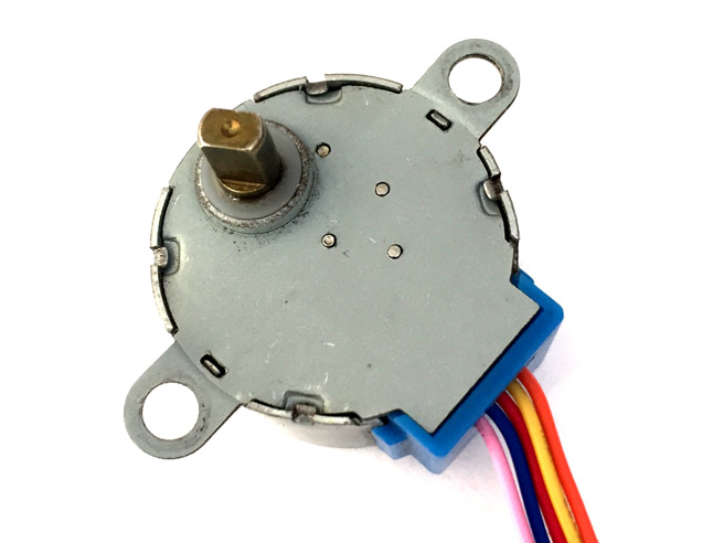
2-28BYJ-48 – 5V Stepper Motor
3-ULN2003 Stepper Motor Driver
The DE10-Lite presents a robust hardware design platform built around the Altera MAX 10 FPGA. The MAX 10 FPGA is well equipped to provide cost-effective, single-chip solutions in the control plane or data path applications and industry-leading programmable logic for ultimate design flexibility.

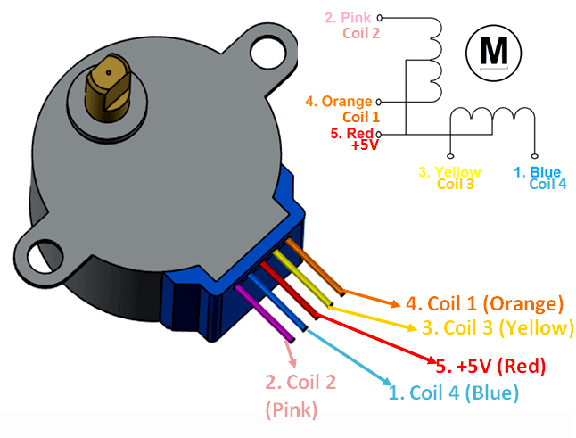
The 28BYJ-48 is a 5-wire unipolar stepper motor that runs on 5 volts. The exciting thing about this motor is that people have been using it in countless applications over the last few decades. It is used in air-conditioners, vending machines, and many other applications.
One of the best things about these motors is that they can be positioned accurately, one 'step' at a time. The other advantage is that they are relatively precise in their movement, and they are pretty reliable since the motor does not use contact brushes.
They generally give good torque even in the stand-still state, which is maintained as long as power is supplied to the motor. The only downside is that they are hungry for power and consume power even when they are not moving.

The power consumption of the motor is around 240mA. Because the motor draws too much power, it is best to power it directly from an external 5V power supply rather than drawing it from the FPGA. However, I decided to plug it directly into the board for this project due to a lack of an external power source.
The motor usually comes with a ULN2003 based driver board. The ULN2003 is one of the most common motor driver ICs, consisting of an array of 7 Darlington transistor pairs, and each pair can drive loads of up to 500mA and 50V. Therefore, four out of seven pairs are used on this board.
The board has a connector that perfectly mates the motor wires, making it very easy to connect the motor to the board. There are also connections for four control inputs as well as power supply connections. The board has four LEDs that show activity on the four control input lines (to indicate a stepping state). They provide a nice visual when stepping.
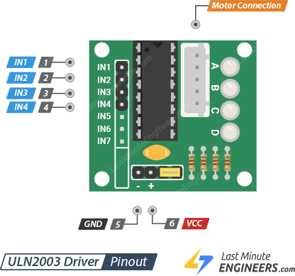
IN1 – IN4 pins are used to drive the motor. Connect them to digital output pins on the FPGA.
GND is a standard ground pin.
VDD pin supplies power for the motor. Connect it to an external 5V power supply. Because the motor draws too much power, you should NEVER use the 5V power from your FPGA to power this stepper motor. However, I connected it directly to the board because I do not have an external power supply at home.
Motor Connector This is where the motor can be plugged into the board. The connector only goes in one direction.
For the final project I interconnected the 3 main components as shown in the image bellow:

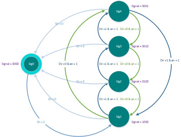
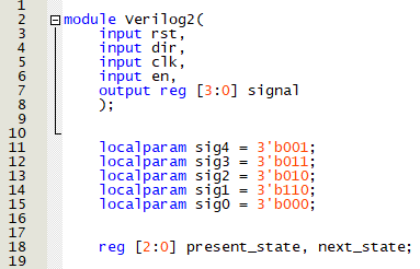
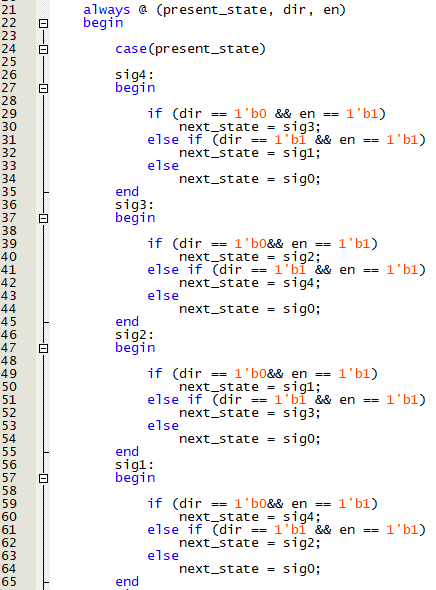
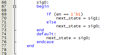
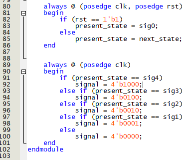
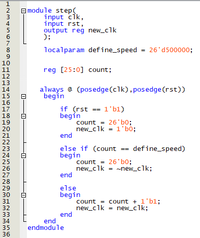
The main functionality of this project revolves around a Finite State Machine that provides the logical PWM output to control the stepper motor by controlling its coils individually. In addition, it also allows changing the direction of the motor's rotation. The Finite State Machine is as follows:
After writing and compiling the codes on Quartus, I created a block diagram for each code and connected it accordingly:

After connecting the blocks, I assigned the pins for the FPGA to inputs and outputs as follows:
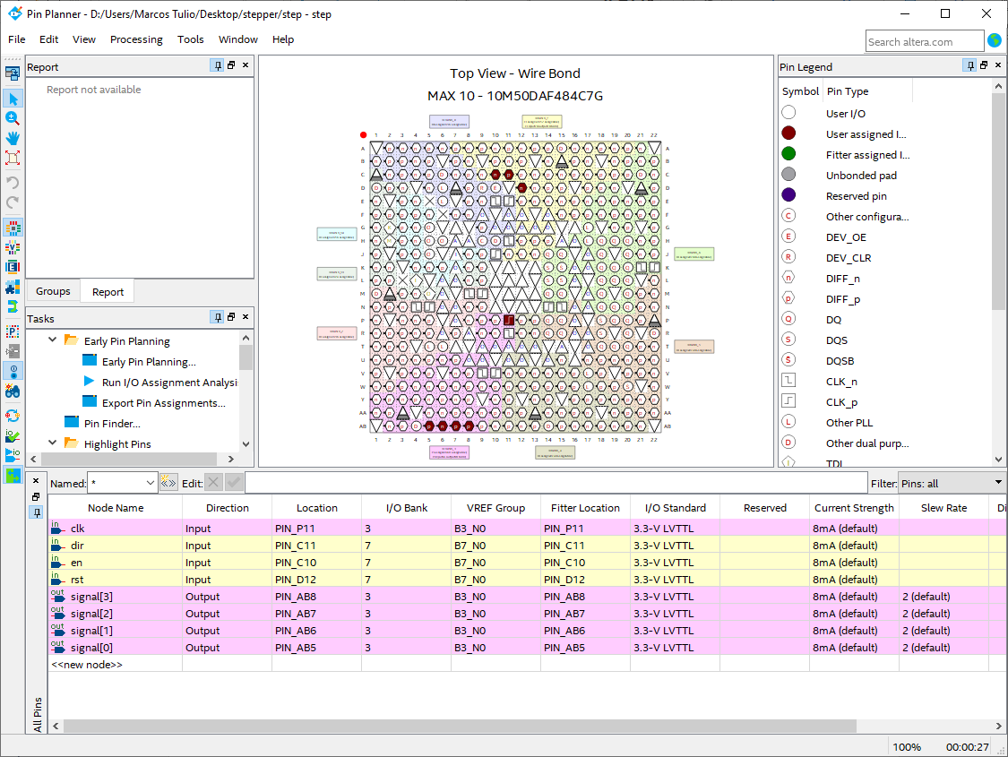
Where:
1-PIN_P11 corresponds to the 50MHz internal clock of the FPGA.
2-PIN_C11 corresponds to Switch 1 of the FPGA and controls the direction of rotation forthe motor.
3-PIN_C10 corresponds to Switch 0 of the FPGA and turns the circuit on or off (Enable).
4-PIN_D12 corresponds to Switch 2 of the FPGA and resets the entire circuit.
5-PIN_AB8 corresponds to Digital Pin 3 of the Arduino connector of the FPGA.
6-PIN_AB7 corresponds to Digital Pin 2 of the Arduino connector of the FPGA.
7-PIN_AB6 corresponds to Digital Pin 1 of the Arduino connector of the FPGA.
8-PIN_AB5 corresponds to Digital Pin 0 of the Arduino connector of the FPGA.
